Concept ~ Design ~ Build ~ Fly ~ Produce
As a Project I started in the mid 90’s, THIS wing has a place in the commercial world! On this page, I am going to document every step of the development of Phase VI. From the beginning, it has been about Aerial Photography, but with today’s technology, multi-mission capability is not just possible, but greatly enhances the Results.
Mission: Data Recon, Payload Delivery, Search & Rescue
Concept
Fixed Wing, and Lowest possible drag, with a Span Constraint.
The Holy Grail of Flight, is to Fly Fast and Fly Slow, while maintaining a Utility.
Safety always tops the list, so it is built into the design.
Autonomous Flight Mission. The operator builds the flight plan on a laptop computer, uploads the plan to the plane, and hand launches it. Upon mission completion, the plane will return to the launch site, and land itself. Save the Flight Plan, and repeat it.
GPS Navigation
Redundant Navigation, in a 3D World. When activated, using LIDAR, a 3 dimensional world is built as the plane is en route to the site, so if GPS is lost, the plane can find it’s way home.
Build and Market an easy to use System, with a variety of ‘Plug in Wings’, depending upon the Mission.
Superior to a Quad Copter in Many ways, with a Longer Duration Flight means more distance can be covered, Larger Payload and Quieter to mention a few.
Here is what I call my ‘Napkin Drawing’:

Design
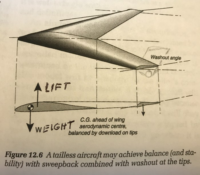
A ‘Wing’ is the most aerodynamically efficient aircraft – least amount of Drag. A drawback, is that it can be unstable in Yaw, hence the wingtip fins, that serve Triple purpose: Yaw Damping, Camera Location and Landing Skid. Another drawback, is it unstable in Pitch, unless the Wingtips have 3 to 5 degrees of Washout, which can be referred to as ‘Trim Drag’. In an effort to reduce this trim drag, a ‘Dynamic Center of Gravity’ will be incorporated. By actively moving the center of gravity Aft, to coinside with the ‘Lift’ (center of pressure), the need for washout will be reduced, thus, reducing drag.
Missions:
*Admiring the beauty of the landscape
*Planning / Monitoring / Mapping a property development
*Search & Rescue, with 3 video downlinks to 3 separate monitors
*Build a 3D World of city streets and buildings using LIDAR, so Package delivery is possible.
*Package Delivery
*Pipeline or Electric Line Inspection, using FLIR data collection
*BVLOS (Beyond Visual Line of Sight)
LIDAR – A surveying method that measures distance to a target by illuminating the target with pulsed laser light and measuring the reflected pulses with a sensor.
Data Collection from Three Locations – 1) Nose 2) L/H Wing Tip 3) R/H Wing Tip Some of the results can be Stereo Vision
WingTip Cameras Nose, or, Pilot Eye Camera


Thrust Vectoring – Pitch Control – Yaw Control


Rotating Twin Fan Motors – Rotated at 45 degrees, the Fans can carry a considerable weight, thus slow flight / loiter is possible.
Dynamic Center of Gravity – Pitch Control – Slower Take-Off and Landing – Slow Flight (Loiter). Birds shift their weight for pitch control – Dynamic Center of Gravity !
Wing Tip Fan for Pitch Control and Roll Control – Eliminate all the moving parts and servo’s, associated with Elevons. Tip Fans run in ONLY One Direction. They are Always Running at low speed to Maintain the Pressure Differential between the Top of the Wing and the Bottom of the Wing. Fans Increase speed with Aileron Input to Lift That Wing. Pitch Up command Stops Both Fans to pitch the nose up. Pitch Down command Increases the speed of Both Fans to pitch the nose down. Take-Off: Both Fans are at Full Power to Carry some of the Weight with the C of G moved Aft.


Tow Hook Release – Center: Tow Sail Planes, Banners, Long Ribbons.
Tow Hook / Payload Release – R/H and L/H
Safe to Fly Over People – 1) No Exposed Blades 2) In the event of a Thrust Failure, it can Glide to a Suitable spot to land or Deploy the BRS (ballistic recovery system).
Incorporate all the design features, into a package that is easy to use, and has a High Return on Investment (ROI).
Develop a design that lends itself to a High Rate of Production, using 3D printed parts.
All Copyrights and Patents Maintained by Chuck Gantzer
Build
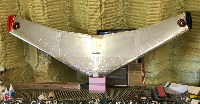
Flight Test is a very risky business. I’m building Five flight test models, with the same planform – Swept Wing, with Wingtip Fins.
v.1
Attain a Planform


Wire Cut White Foam / Packaging Tape Wing Skin – Built by Judd & Chuck
Vertical Fins – Canted outboard 10 degrees
BB (Bare Bones) First Flight 7/9/18
Purpose:
1) Locate CG Range
2) Develop the Atlatl
3) Develop the Catapult Launch
Possible Revisions:
Convert to Prandle Type Wing, with Two 50mm Fan Motors, and Torque Wing Tips.
Convert to a Towable SailPlane.
v.2
Mini Wing
Re-locate vertical fins to the Butt Ends of the Wing
Wire Cut White Foam / Contact Cement/ Light Weight Dacron Fabric
Elevons
Purpose:
- Develop the Pitch Flight Control System
a) Pitch Control – Contain the entire battery load in one movable slide, along the Longitudinal Axis.
b) Roll Control – Elevons
- Develop the Dynamic Center of Gravity
v.3
Wire Cut Blue Foam / Omni Direction Fiberglass Spars
Motors – Alex’s A10 Motor
EDF (electric ducted fan) 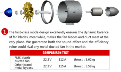
Radio – JR 347 Flight Controller Radio
Purpose:
Develop Wing Tip Fin / Camera Configuration
Flight Test Control and Propulsion System
a) Pitch Control – Locate the end points of the CG range
b) Roll Control – Locate Voltage Points of the Roll Motors
Flight Test Wing Tip Fans –
Static test showed some promise.
Flight Test Dynamic Center of Gravity –
Static Test showed less CG change than I though.
v.4


Fiberglass Spars – wet layup
Wire Cut Blue Foam – 2” for the wings; 3” for the center section
Omni Direction Fiberglass Spars
Motors – Two Freewing 64mm 12-Blade EDF 4S Power System w/ 2836-3300kv Motion RC


ESC – Two E-flite EFLA1140W 40-Amp BEC Programable Brushless ESC Horizon
Batteries – Two: Admiral 2400mAh 3S 11.1v 30C Motion RC
Radio – FrSky Horus X10 Flight Controller Radio
Receiver – FrSky G-RX8
Purpose:
Flight Test:
Flight Control
a) Pitch Control – Dynamic Center of Gravity – Locate the end points of the CG range, and set the end points of the servo controlled, sliding battery.
b) Roll Control – Wing Tip Fans (from a video card) Locate Voltage Points of the Roll Motors
Develop:
Ballistic Recovery System (BRS)
Three Data Collection Points
Propulsion System
Payload Deploy
Tow Hook Release
v.5


PixHawk 4 – Flight Controller – PX4 does not require a remote control system for autonomous flight modes. You can disable RC checks.
Fiberglass Spars – wet layup
50% Spar – Hardpoint Station where Structure comes together.
Rotate Motors for Take-Off, Land, and Loiter
Wire Cut Blue Foam / Balsa-Plywood-Omni Direction Fiberglass Spars / Motors & Flight Controller / Plug In Wings / PowerUp Camera for First Person View (FPV)
Motors – Two 11-Blade Ducted Fan with mounts (blade tips are closer) KV2840-3150 Predator Motor, 64mm (FMMDF003) Horizon
ESC – Two: Ztw MANTIS 45A SBEC5A 2-6 Lipo/5-18 NiMH Programable Brushless ESC Motion RC
Batteries – Two: Admiral 2200 mAh 4S 14.8v 35C Motion RC
Radio – FrSky Horus X10 Flight Controller Radio
Receiver – FrSky G-RX8
Purpose:
Three Data Collection Points
Do a Splash of All the Sections, to Build a Female Mold, for Blow In Styrofoam, or 3D print.
Develop Plug In Wings – Different wing packages can be interchanged, depending on the mission.
Develop Stackable Take-Off
A remote control (RC) radio system is required if you want to manually control your vehicle (PX4 does not require a radio system for autonomous flight modes).
Three Release Points – Center, R/H and L/H.
v.6


Autonomous Flight – PX4 does not require a remote control system for autonomous flight modes. You can disable RC
Fiberglass Spars – wet layup
Rotate Motors for Take-Off, Land, and Loiter
Motors – Two 11-Blade Ducted Fan with mounts (blade tips are closer) KV2840-3150 Predator Motor, 64mm (FMMDF003) Horizon
ESC – Two: Ztw MANTIS 45A SBEC5A 2-6 Lipo/5-18 NiMH Programable Brushless ESC Motion RC
Batteries – Two: Admiral 2200 mAh 4S 14.8v 35C Motion RC
Radio – FrSky Horus X10 Flight Controller Radio
Receiver – FrSky G-RX8
Purpose:
Three Data Collection Points Develop Canopy Deploy and Retract
Develop a female mold for High Rate production models
Develop 3D printed Fin Wing Camera (FWC) part.
Develop 3D printed Center Section
A remote control (RC) radio system is required if you want to manually control your vehicle (PX4 does not require a radio system for autonomous flight modes).
Three Release Points – Center, R/H and L/H.
